
 Request A Quote

Traffic Signal Pole Specification Guide for Urban Road Projects
 FACEBOOK
 TWITTER
 LINKEDIN
A traffic signal pole carries dynamic, safety-critical equipment above live traffic. Its design must account for signal heads, mast arms, signs, cameras, detectors, cable loads, wind, fatigue, deflection, foundation behavior, corrosion, electrical bonding and maintenance access. Procurement should begin with a complete loading schedule and local road-authority requirements, not a generic pole height and arm length.
| DIRECT ANSWER Specify the traffic signal pole as a complete engineered assembly. Provide the governing code, design wind data, arm geometry, signal and sign loads, allowable deflection, fatigue category, material and coating, cable routing, handholes, anchor bolts, foundation and installation tolerances. Require calculations and drawings for the exact configuration supplied. |
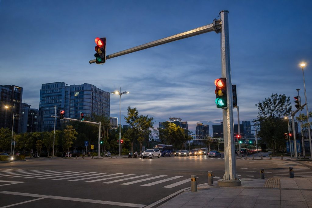
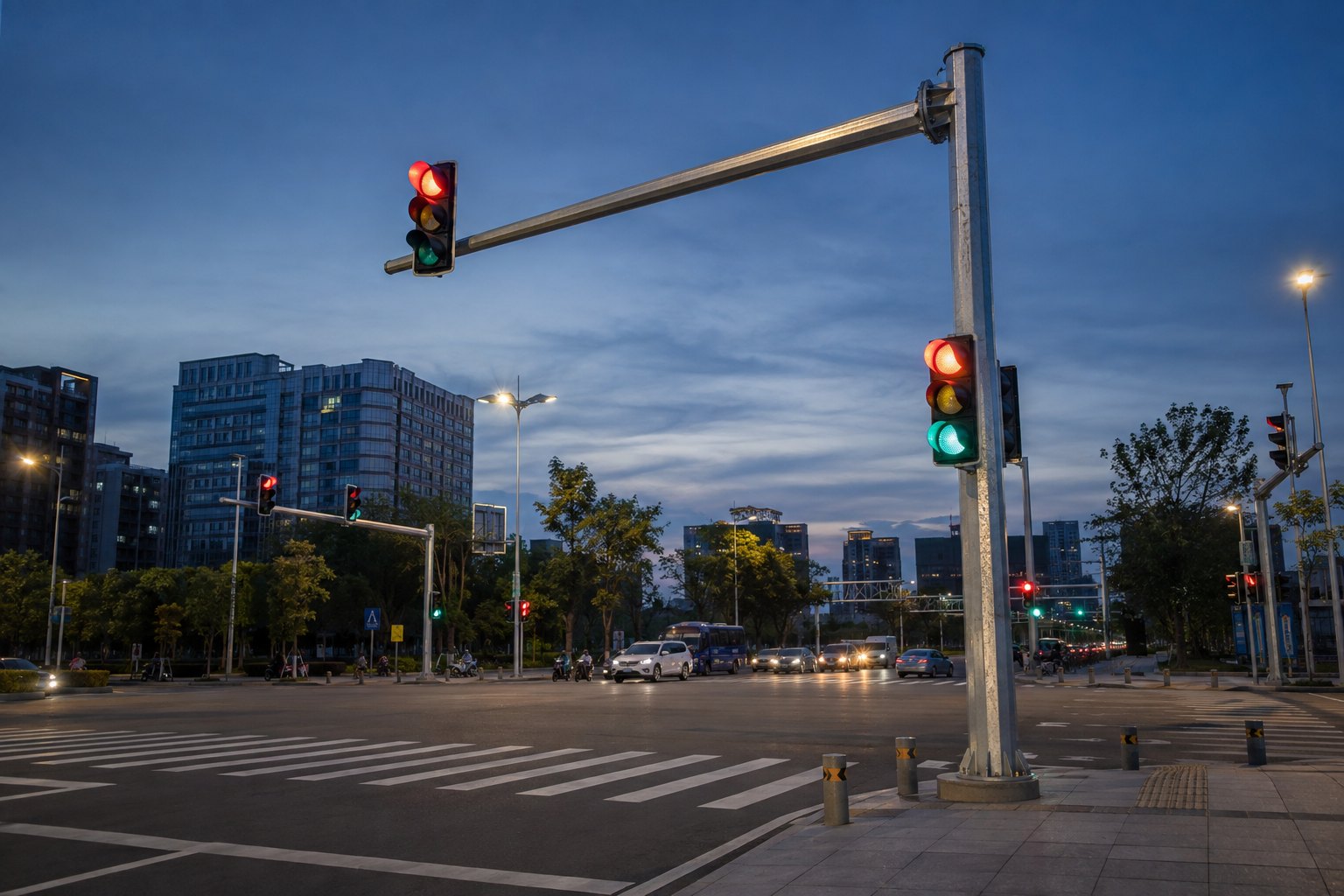
A mast-arm traffic signal pole must coordinate signal visibility, lane geometry, clearances, maintenance and structural loading.
Build the Load Schedule Before Selecting the Pole
A signal head, illuminated sign or camera changes the projected area and moment on the shaft, arm, connection and foundation. List every component with its position, mass, dimensions and effective projected area. Include future equipment only when the authority requires reserved capacity. Our engineering team also asks whether the arm supports internally routed cable, overhead detection, streetlights or backplates because these details affect both structural and electrical design.
| Mounted item | Information required | Structural effect | Coordination issue |
| Signal head/backplate | Quantity, size, mass, EPA, position | Arm bending and torsion | Visibility and cable drops |
| Road sign | Panel area, offset and mass | Often significant wind load | Lane assignment and clearance |
| Camera/detector | Bracket, mass, projected area | Local vibration and fatigue | Field of view and service access |
| Street luminaire | Outreach, mass, EPA and tilt | Additional shaft and base moment | Lux, glare, surge and wiring |
Wind, Fatigue and Deflection Are Separate Checks
Strength under design wind
Use the required wind code, basic wind speed, exposure category, gust or dynamic provisions and importance level. The calculation should cover shaft, mast arm, connections, base plate, anchor bolts and foundation reactions. Coastal typhoon zones, open desert corridors and junctions on exposed terrain can have very different wind conditions even within one city.
Fatigue from repeated oscillation
Traffic mast arms experience many load cycles. Galloping, vortex shedding, natural wind gusts and truck-induced pressure pulses may control connection details long before a one-time maximum wind event. Require the fatigue category and design method specified by the road authority. Pay close attention to weld toes, handholes, arm-to-shaft connections and other stress concentrations.
Serviceability and signal alignment
A pole can remain below its strength limit yet deflect or rotate enough to affect signal visibility and appearance. State allowable vertical and horizontal deflection, arm rotation and residual alignment. The supplier needs these limits before sizing the structure.
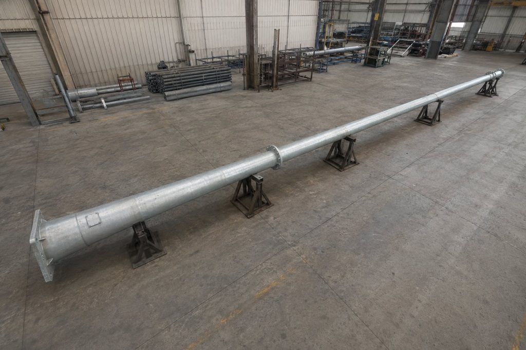
Full-length traffic-pole components should be checked for taper, connection geometry, flange alignment and surface condition.
Foundation, Anchor Bolts and Underground Coordination
The foundation design needs the pole reactions and a geotechnical model. Check soil layers, groundwater, buried services, excavation limits, concrete and reinforcement, bolt embedment, conduit bends, drainage and finished pavement. An anchor-bolt template should hold the bolt circle and projection during the pour. Survey the foundation before the pole arrives; field slotting or heating of a base plate is not an acceptable correction.
Position conduits so cables can be pulled without sharp bends and without blocking access to nuts. Separate power and communications where required. Provide an accessible earth connection and coordinate surge protection for the signal controller, luminaires, cameras and long exposed conductors.
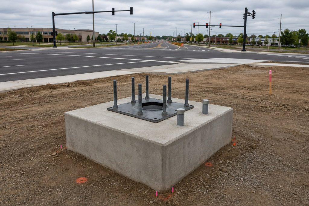
A pre-erection survey checks bolt circle, projection, conduit positions, concrete level and junction geometry.
Material, Galvanizing and Access Details
Traffic poles are commonly fabricated from steel because the material supports stiff shafts, long arms and welded attachments. Define the steel grade, seam orientation, weld procedures, nondestructive testing where required and hot-dip galvanizing standard. If paint is added, specify the complete duplex system and color control. Vent and drain holes must support galvanizing and prevent trapped water in service.
Handholes need reinforced openings, durable covers, tamper-resistant fasteners where appropriate and enough working space for the intended terminals. Coordinate the door orientation with pedestrian paths and live traffic so maintenance crews do not stand in a lane. Any luminaire mounted on the pole should have the project IP, IK, CRI, beam and thermal requirements confirmed separately.
Traffic Signal Pole Procurement Comparison
| Configuration | Best fit | Primary advantage | Critical risk |
| Vertical signal pole | Compact junction or roadside head | Simple structure | Visibility and roadside clearance |
| Single mast arm | One-direction lane control | Clear overhead placement | Arm deflection and fatigue |
| Long or multi-head mast arm | Wide multi-lane approach | Fewer roadside supports | Wind area, torsion and foundation |
| Combination signal-lighting pole | Constrained urban junction | Combines functions | Higher load and electrical complexity |
Submittal and Inspection Checklist
- Authority-approved geometry showing lanes, stop line, signal-head positions, arm length, clearances, handholes, conduits and maintenance access.
- Complete attachment schedule with mass, dimensions, EPA, offsets and future reserved loads where required.
- Signed structural calculation for wind, fatigue, deflection, connections, base plate, anchor bolts and foundation reactions under the governing code.
- Fabrication drawings, material certificates, welding and NDT records, galvanizing/paint reports, dimensional inspection and packaging plan.
- Foundation and anchor survey, erection method, bolt-tightening procedure, grounding and insulation tests, alignment record and final as-built documents.
Mistakes That Create Expensive Site Corrections
Problems usually begin at interfaces: a sign grows after the pole is designed, signal heads move without recalculation, the foundation drawing uses the wrong bolt circle, conduits clash with anchor rods, or the arm connection cannot be assembled from the available lane closure. Freeze equipment positions before fabrication and hold a coordinated drawing review with civil, traffic, electrical and structural teams.
FAQ: Questions Buyers Ask
What is a traffic signal pole?
It is a structural support for traffic signal heads and related equipment such as mast arms, signs, detectors, cameras or luminaires. The exact assembly must be designed for its site, loads and governing road-authority standard.
How tall is a traffic light pole?
Height depends on signal placement, road geometry, vehicle and pedestrian clearance, mast-arm depth and local authority rules. Use the approved junction layout rather than a generic catalog height.
Why do traffic signal mast arms need fatigue design?
Wind and vehicle-induced pressure can create repeated oscillation. These cycles concentrate stress at welds, openings and connections, so fatigue can govern even when static wind strength is adequate.
What documents should a traffic signal pole supplier provide?
Request calculations, fabrication drawings, material and welding records, coating reports, dimensional inspections, foundation reactions, installation instructions and as-built acceptance records required by the authority.
Coordinate the Junction Before Releasing Fabrication
| PROJECT REVIEW For a traffic-signal project, share the approved junction layout, equipment load schedule, mast-arm geometry, wind and fatigue criteria, soil report, foundation scope, coating requirement, electrical details and applicable authority standards. |
Send the site plan, target lux, mounting heights, operating schedule, environmental conditions, and electrical data through the Dawn Lighting official inquiry page. The engineering team can review the design basis and prepare a project-specific DIALux proposal and B2B quotation.
- 10 Meters Lamp Post
- 10 Meters Pole
- 1000w Led Projector
- 100W LED Tunnel Light
- 12 Meters Lamp Post
- 12 Meters Pole
- 1200w Led Projector
- 15 Light Pole
- 1500w Led Projector
- 150W LED Tunnel Light
- 1800w Led Projector
- 2 In 1 Solar Flood Light
- 200w Led Tunnel Light
- 50w Led Tunnel Light
- 6 Meters Lamp Post
- 6 Meters Pole
- 8 Meters Lamp Post
- 8 Meters Pole
- 800w Led Projector
- 80w Led Tunnel Light
- Colourful Decorative Light
- Conical post
- Courtyard Lamp
- courtyard light
- courtyard lighting fixture
- Decorative Landscape Light
- Decorative road Light
- Flood Light For Courtyard
- Flood Light for Garden
- Flood Light For Outdoor
- Foot Led High Bay Lights
- high bay led lights 100w
- industrial lampshade
- industrial LED shed lights
- industrial magnifying glass with light
- Integrated Solar Flood Light
- led courtyard lamp
- led courtyard light
- led high bay light 100w
- LED Projector For Stadium
- Led UFO High Bay 150W 5000k
- Lighting Plants Mining Price
- Maintenance Free LED Street Light
- Pic Controlling Tunnel Light
- PLC controlling tunnel light
- Post Top Garden Light
- RGB Landscape Light
- Rgbw Decorative Light
- Smart Tunnel Light
- solar courtyard lamp
- solar courtyard light
- Solar LED Road Light
- Solar Street Light For 10 Meter Pole
- Solar Street Light For 12 Meter Pole
- Solar Street Light For 6 Meter Pole
- Solar Street Light For 8 Meter Pole
- Split Type Solar Flood Light
- Sporting Projector
- Stadium Led Projector
- Street Lighting Post
